blogu

Dom

blogu

  • The Ultimate Guide to Ball Valves and How to Choose Them | GEKO Valve
    The Ultimate Guide to Ball Valves and How to Choose Them | GEKO Valve
    Oct 28, 2026
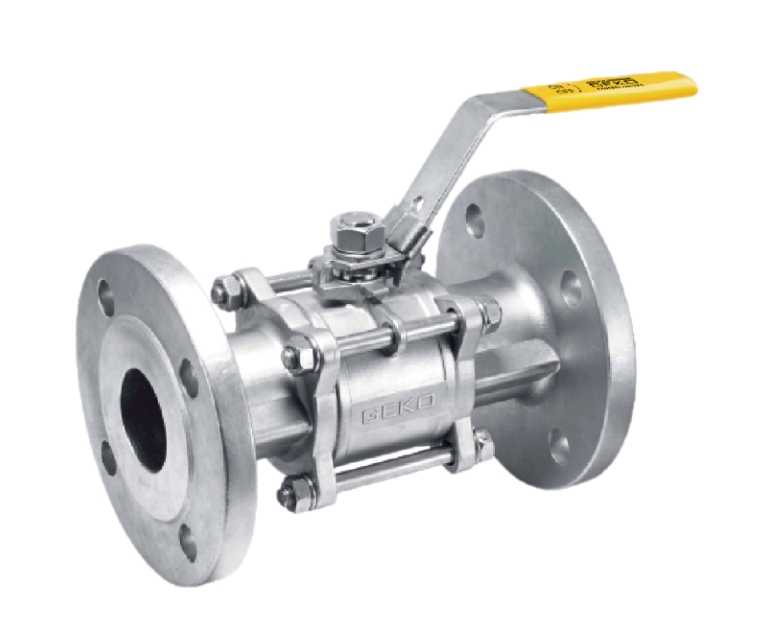
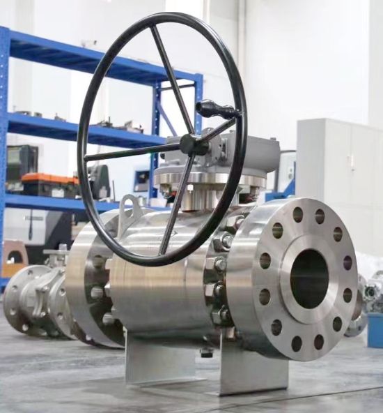
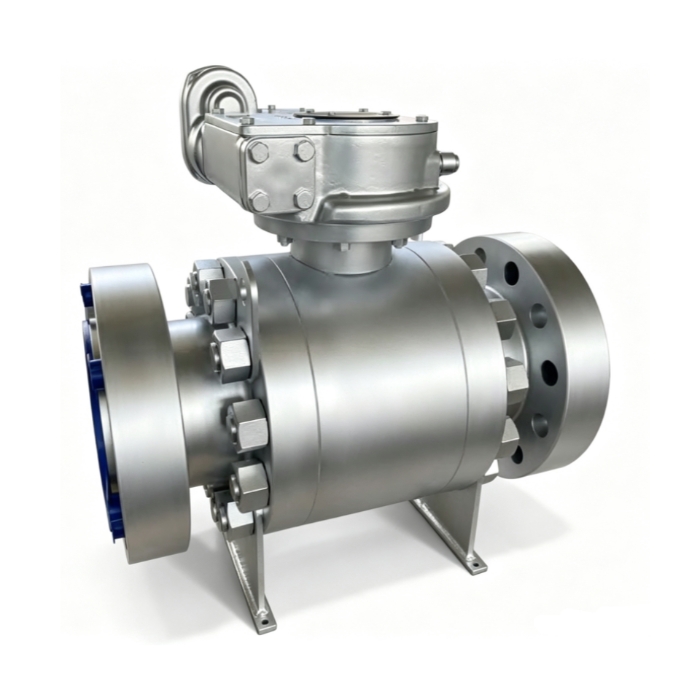
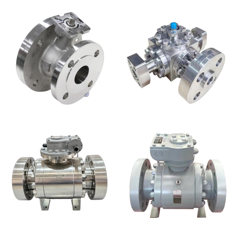
    The Ultimate Guide to Ball Valves and How to Choose Them | GEKO Valve Ball valves are among the most widely used quarter-turn fluid control devices across industrial piping systems. Known for fast operation, reliable sealing, low maintenance and compact structure, they serve critical isolation and flow regulation tasks in water treatment, oil & gas, chemical processing, power generation and many other sectors. This complete guide covers ball valve basics, common types, key specifications and practical selection rules to help you pick the right ball valve for your working conditions. What Is a Ball Valve? A ball valve uses a hollow, perforated rotating ball inside the valve body to control fluid flow. When the ball’s bore aligns with the pipeline, the valve opens and media passes through. Rotating the ball 90 degrees blocks the passage, shutting off flow. Most standard ball valves are designed for tight shut-off, though special designs support throttling service. GEKO Valve delivers a full lineup of ball valves built to deliver dependable sealing and long service life for industrial projects.   Common Types of Ball Valves Floating Ball Valve – The ball is not fixed by upper and lower trunnions. Fluid pressure pushes the ball against the downstream seat to form a seal. Ideal for medium and low pressure applications, simple structure and cost-effective. Trunnion Mounted Ball Valve – The ball is supported by fixed trunnions at top and bottom. Sealing force does not rely fully on line pressure. Suitable for high pressure, large size and heavy-duty industrial pipelines. Top Entry Ball Valve – Maintenance can be carried out directly on site without removing the whole valve from the pipe. Preferred for critical pipelines where shutdown and disassembly are costly. Side Entry (Split Body) Ball Valve – The body is split into two or more parts for easy assembly. Widely used for general industrial and water service. Full Port vs Reduced Port Ball Valve – Full port ball valves have a bore size matching the pipe inner diameter, minimizing flow resistance and pressure drop. Reduced port ball valves feature a smaller bore, lower cost and compact size for non-critical flow loss scenarios. Lined Ball Valve – Lined with PFA, PTFE or other corrosion-resistant materials, for handling strong acids, alkalis and aggressive chemical media. Key Components of a Ball Valve Valve Body: The main pressure-containing shell; common materials include WCB, A105, 304 stainless steel, 316 stainless steel, duplex steel and alloy steel. Ball: The rotating closure member, available in stainless steel, carbon steel, hard-faced alloy for abrasive service. Seat & Sealing Insert: PTFE, RPTFE, Viton, Devlon, metal seat for high temperature or fire-safe requirements. Stem: Transmits torque from the handle or actuator to the ball; anti-blowout stem design is a standard safety feature on GEKO Valve ball valves. Operator: Manual lever, gearbox, pneumatic actuator, electric motor operator (MOV) for automated control. Main Industrial Applications Oil and gas: wellhead isolation, pipeline transmission, refining and storage terminals Chemical industry: corrosive chemical transfer, batch processing and reactor isolation Water treatment: raw water, clean water, sludge and wastewater pipelines Power plants: cooling water, steam auxiliary systems and compressed air lines Food and beverage: sanitary ball valves for hygienic media Hydrogen and clean energy: low-leakage ball valves for hydrogen storage and transportation How to Choose the Right Ball Valve: Step-by-Step Checklist 1. Confirm Media Properties Identify the fluid: water, oil, gas, acid, alkali, slurry or hydrogen. Corrosive media require stainless steel or lined construction. Slurry service needs hard-faced balls and wear-resistant seats to avoid abrasion damage. The technical team at GEKO Valve can assist with material matching for challenging media. 2. Working Pressure and Temperature Match the valve pressure class (Class 150, 300, 600, 900 etc.) to your maximum operating pressure. Check temperature limits: soft seats work well at moderate temperatures, while metal-seated ball valves handle high temperature and fire-safe service. 3. Valve Size and Flow Requirement Select full port if low pressure drop is essential. Reduced port is acceptable when flow loss is not a concern. Confirm connection ends: flange, threaded, butt weld or socket weld to match your piping. 4. Operation Type Manual lever: simple, low cost, for infrequent operation Gear operated: for large size or high torque valves Pneumatic actuator: fast on/off, suitable for automatic control systems Electric actuator: ideal for remote control and slow switching 5. Sealing and Safety Requirements Soft seats provide bubble-tight shut-off for most general service. Metal-to-metal seats are selected for high temperature, fire-safe, abrasive or high cycling conditions. Fire-safe certification and low-emission stem packing are available for hazardous media. 6. Industry Standards Common standards include API 6D, ASME B16.34, ISO 17292. Confirm whether you need special tests such as fugitive emission test, hydrostatic test and cryogenic test. Advantages and Limitations of Ball Valves Advantages 90-degree quick open and close, easy operation Excellent tight shut-off performance Simple structure, fewer wearing parts, long service life Wide range of material options for different media Limitations Standard soft-seated ball valves are not recommended for continuous heavy throttling High temperature may degrade soft seat materials Trunnion and large-size ball valves come with higher cost Final Selection Tips Never choose a ball valve only by nominal size and pressure rating. Always evaluate media corrosion, temperature cycling, actuation frequency and safety codes. If you work with hazardous or high-value media, prioritize certified low-leakage and fire-safe designs. For long-term reliability, match body, ball and seat materials as a complete set rather than mixing incompatible materials. Reach out to GEKO Valve for technical support when you are unsure about your selection. Conclusion Ball valves are versatile, dependable fluid control components, but proper selection directly determines system safety and service life. This guide walks you through core types, construction, application scenarios and critical selection criteria. When you clarify your media, pressure, temperature, operation mode and standard requirements, you can efficiently narrow down the correct ball valve model for your piping project. Target Keywords GEKO ball valve, trunnion ball valve, floating ball valve, stainless steel ball valve, PTFE seat ball valve, fire safe ball valve, full port ball valve, industrial ball valve, low emission ball valve
    CZYTAJ WIĘCEJ
  • Ball Valve Materials Guide for Corrosion Resistance and Durability | GEKO Valve
    Ball Valve Materials Guide for Corrosion Resistance and Durability | GEKO Valve
    Oct 20, 2026
    Ball Valve Materials Guide for Corrosion Resistance and Durability Corrosion and premature wear are two leading causes of ball valve failure in chemical processing, offshore, water treatment, and oil & gas piping systems. Selecting the correct ball valve materials directly determines long-term durability, sealing integrity, safety, and total cost of ownership. A ball valve built with incompatible alloys or seat materials can suffer pitting, crevice corrosion, chemical attack, or seal degradation, leading to fugitive emissions, unplanned shutdowns, and expensive replacement. This GEKO Valve guide breaks down body, ball, liner, and seat materials by corrosion performance, service limits, and suitable industrial applications, helping engineers specify valves that last in aggressive process media. Why Corrosion Resistance and Material Durability Matter for Ball Valves Unlike generic piping components, ball valves contain wetted parts that stay in continuous contact with process fluids — acids, alkalis, brine, chlorides, solvents, and sour media. Even minor corrosion can lock the rotating ball, damage sealing surfaces, and break pressure containment. Durability does not only mean mechanical strength; it combines corrosion resistance, temperature stability, abrasion resistance, and resistance to cyclic operation. The optimal material balances chemical compatibility, pressure rating, temperature range, and project budget rather than defaulting to the most expensive superalloy.   Common Ball Valve Body Materials for Corrosive Service WCB Carbon Steel WCB is the standard cast carbon steel for general-purpose ball valves. It delivers high mechanical strength and pressure resistance but offers limited corrosion resistance. Carbon steel is suitable for clean oil, steam, natural gas, and non-corrosive water. In corrosive environments, WCB ball valves rely on internal PTFE or PFA lining to isolate the metal body from aggressive media. Without lining, carbon steel will rust rapidly in damp, acidic, or chloride-rich conditions. 304 / 316L Stainless Steel (CF8 / CF3M) 304 stainless steel works well for low-chloride fresh water, food-grade fluids, and mild alkaline solutions. 316L stainless steel adds molybdenum, greatly improving resistance to chloride ions, dilute acids, wastewater, and common organic solvents. The low-carbon 316L grade avoids intergranular corrosion after welding, making it the most widely specified stainless steel ball valve for moderate corrosion duties. It remains the baseline anti-corrosion choice for water treatment, pharmaceutical, and general chemical lines. 2205 and 2507 Duplex Stainless Steel Duplex stainless steel combines austenite and ferrite microstructures for superior chloride corrosion resistance and higher strength than 316L. 2205 duplex handles brine, brackish water, and moderate seawater service. 2507 super duplex offers outstanding pitting and stress corrosion cracking resistance for seawater desalination, coastal chemical plants, and produced water pipelines where standard 316L will fail over time.   High-Performance Alloys: Hastelloy C276, Monel 400, Inconel 625 Hastelloy C276 resists strong oxidizing acids, chlorine, hypochlorite, and mixed corrosive chemicals, widely used in chlor-alkali and fine chemical processes. Monel 400 provides excellent resistance to hydrofluoric acid and seawater. Inconel 625 is selected for high-temperature corrosive media and thermal fatigue conditions. These nickel-based superalloys deliver extreme corrosion protection but carry a much higher material cost and longer lead times. PTFE / PFA Lined Ball Valves Lined ball valves use a carbon steel or stainless steel shell with a continuous fluoropolymer liner covering all wetted surfaces. PTFE and PFA are nearly chemically inert against most concentrated acids, bases, and aggressive solvents. PFA offers better permeation resistance and higher-temperature stability than PTFE. Lined ball valves are a cost-effective alternative to exotic alloys for strong corrosive media at moderate pressure ranges. Ball and Seat Materials: The Critical Sealing Interface Body alloy protects the valve shell, but the ball and seat form the sealing interface that controls leakage and cycle life. Seat material failure is one of the most frequent durability issues in corrosive ball valves. Virgin PTFE: Universal chemical resistance, compatible with almost all corrosive media. Drawback: cold flow under sustained pressure, which can degrade sealing after long static hold periods. RPTFE (Reinforced PTFE): Filled with glass, carbon, or graphite to reduce creep and boost wear resistance while retaining broad chemical compatibility. It is the most popular upgrade over pure PTFE. PEEK: Excellent combination of corrosion resistance, high temperature capability, and mechanical durability for high-cycle and high-pressure chemical service. Viton / EPDM: Elastomer seats for specific media; Viton suits oils and hydrocarbons, EPDM works for hot water and weak acids. Both are limited against strong solvents and concentrated acids. Metal Seat with Stellite Coating: Hardened metal sealing surfaces for high temperature, abrasive slurry, and fire-safe service. Metal-sealed ball valves rely on alloy selection for corrosion resistance and do not provide bubble-tight shutoff like polymer seats. Key Selection Checklist for Corrosion Resistance & Durability Before finalizing ball valve materials, verify these application parameters: Full chemical composition of the process fluid, including trace chlorides, solids, and oxidizers Operating temperature and pressure, plus upset and thermal cycling conditions Flow velocity and abrasive particles that cause erosion wear Shutoff requirement: bubble-tight soft seat or fire-safe metal seat External environment: coastal salt spray, humid air, or underground burial Maintenance access and expected service life target Common Application Matching Summary Fresh water and mild chemical media → 316L ball valve with RPTFE seat. Seawater and brine → 2205 / 2507 duplex stainless steel. Concentrated acids and aggressive solvents → PFA-lined ball valve. Chlorine and mixed oxidizing chemicals → Hastelloy C276. High-temperature abrasive process → Stellite hard-faced metal seat paired with compatible body alloy. Final Thoughts Durable, corrosion-free ball valve performance comes from matching every wetted component to the process conditions, not just picking a single alloy. GEKO Valve supplies ball valves in carbon steel, stainless steel, duplex, nickel alloy, and PFA/PTFE lined configurations with a full range of seat and ball trim options. Proper material specification reduces corrosion-related failures and extends valve service life in demanding industrial piping systems.
    CZYTAJ WIĘCEJ
  • Ball Valve Materials: Pros and Cons for Industrial Applications | GEKO Valve
    Ball Valve Materials: Pros and Cons for Industrial Applications | GEKO Valve
    Oct 14, 2026
    Ball Valve Materials: Pros and Cons for Industrial Applications Selecting ball valve materials requires careful trade-offs between corrosion resistance, temperature tolerance, mechanical strength, cost and manufacturability. No single material works for every industrial process. Understanding the pros and cons of common ball valve body, ball and seat materials helps process engineers avoid premature failure, unexpected leakage and overspending on overly expensive alloys. This guide compares widely used materials for GEKO industrial ball valves to support faster, smarter valve specification. WCB Cast Carbon Steel & A105 Forged Carbon Steel Pros: High tensile strength, good performance under high pressure and elevated temperatures, affordable price, easy welding and machining. A105 forged carbon steel has denser grain structure, better impact resistance than cast WCB, ideal for critical high-pressure lines, steam and hydrocarbon service. Cons: Poor corrosion resistance. Carbon steel rusts rapidly when exposed to moisture, acids, chlorides and most corrosive chemicals. Not suitable for potable water, brine or continuous wet corrosive service. Impact performance drops sharply at cryogenic temperatures. SS304 / CF8 Stainless Steel Pros: Good general corrosion resistance for clean water and weak alkaline media, oxidation-resistant at moderate heat, easy to sanitize, cost-effective stainless option. It is widely accepted for sanitary, food and beverage, municipal water and general outdoor piping systems. Cons: Susceptible to pitting corrosion in chloride-containing environments such as seawater and brine. Poor resistance to strong acids. Not recommended for high-salinity or harsh chemical processes. SS316 / 316L (CF8M / CF3M) Stainless Steel Pros: Molybdenum addition improves chloride and mild acid resistance significantly. 316L low-carbon grade resists intergranular corrosion after welding. Versatile for chemical processing, food production, desalination pre-treatment and marine non-seawater circuits. It is the most popular stainless steel for corrosive industrial service. Cons: Still vulnerable to concentrated chloride, hot brine and strong reducing acids. Higher cost than SS304, and it cannot compete with duplex or nickel alloys for severe corrosion environments. 2205 Duplex Stainless Steel Pros: Combines austenitic and ferritic microstructure for high mechanical strength and excellent chloride pitting resistance. Outperforms 316 in brackish water, brine and low-to-moderate acid conditions. More economical than Hastelloy and other nickel alloys for seawater-related applications. Cons: Limited high-temperature operating range; it loses corrosion resistance at excessive heat. Less ductile than austenitic stainless steel and harder to machine. Not suitable for strong reducing acids. PFA / PTFE Lined Materials Pros: Almost universal chemical inertness against strong acids, alkalis and aggressive solvents. The metal shell provides structural strength while fluoropolymer lining isolates corrosive media. Perfect for harsh chemical processing where standard metals degrade quickly. Cons: Lining can be scratched by abrasive slurries. Not compatible with high-temperature steam. Temperature and pressure ratings are lower than solid metal valves, and lined valves are heavier and more expensive than carbon steel alternatives. Hastelloy C276, Alloy 20 and Monel Nickel Alloys Pros: Outstanding resistance to oxidizing acids, sour gas (H₂S), chlorine and many aggressive chemicals. Excellent resistance to stress corrosion cracking and localized pitting. These specialty alloys serve critical, high-risk processes where 316 and duplex steel fail. Cons: Very high raw material and machining costs. Long lead times are common. Nickel alloys are only justified for extreme corrosive conditions, making them impractical for standard water, oil or steam lines. Common Seat & Seal Materials: PTFE, FKM, Metal, PEEK PTFE: Pros — chemically inert, bubble-tight shutoff; Cons — prone to cold flow, limited high-temperature range. FKM (Viton): Pros — resistant to oils, fuels and hydrocarbons; Cons — incompatible with ketones and some strong acids. Metal seat: Pros — suitable for high temperature, abrasive media and frequent cycling; Cons — not bubble tight, higher torque requirement. PEEK: Pros — excellent wear and high-temperature resistance; Cons — premium pricing, limited availability. Quick Comparison Guidance Carbon steel works best for non-corrosive high-temperature steam and oil. SS304 fits clean, low-chloride water and sanitary light-duty service. SS316 balances performance and budget for general corrosive applications. 2205 duplex is the go-to for brine and high-chloride water. Lined valves handle aggressive chemicals, while nickel alloys are reserved for extreme corrosive process conditions. Closing Notes from GEKO Valve Material selection should never rely on cost alone. A cheaper valve that fails early will generate far higher downtime and maintenance costs. Share your medium, temperature, pressure and chemical concentration with GEKO’s engineering team to select a ball valve material that matches your industrial application perfectly.
    CZYTAJ WIĘCEJ
  • Which Ball Valve Material Is Best for Your Application? | GEKO Valve
    Which Ball Valve Material Is Best for Your Application? | GEKO Valve
    Oct 14, 2026
    Which Ball Valve Material Is Best for Your Application? Choosing the correct ball valve material is one of the most critical decisions for process reliability. Even a well-designed ball valve will fail prematurely if its body, ball and seat materials are incompatible with your fluid, temperature, pressure and chemical environment. With options ranging from WCB carbon steel and stainless steel to duplex steel, PFA lining and specialty alloys, engineers and procurement teams need a clear framework to match materials to their exact working conditions. This guide breaks down common ball valve materials, their strengths, limitations and ideal use cases to help you select the right GEKO ball valve for your system. Core Factors That Decide Ball Valve Material Before comparing materials, confirm four key process parameters. The fluid medium and chemical concentration determine corrosion risk. Operating temperature impacts material toughness, creep resistance and seal performance. Working pressure defines wall thickness and mechanical strength requirements. Additional factors include chloride content, abrasive particles, cyclic switching frequency and hygienic requirements for food or pharmaceutical service.     WCB Carbon Steel / A105 Forged Steel Ball Valves WCB cast carbon steel and A105 forged carbon steel are cost-effective, high-strength options for non-corrosive media. They perform reliably at elevated temperatures and suit steam, compressed air, fuel oil and natural gas pipelines in power plants, thermal systems and general oil & gas service. Carbon steel works well from -29°C up to around 425°C, but it rusts quickly when exposed to water, acids or chloride-rich fluids. It is not recommended for wet corrosive service, drinking water or chemical processing lines. SS304 (CF8) Stainless Steel Ball Valves SS304 stainless steel is the standard corrosion-resistant ball valve material for water treatment, clean water, weak alkaline fluids and general outdoor piping. It offers good oxidation resistance and excellent low-temperature toughness, making it popular for general industrial and sanitary applications. SS304 works for low-chloride water but struggles with saltwater, brine and concentrated chloride media, where pitting corrosion will develop over time. SS316 / 316L (CF8M / CF3M) Stainless Steel Ball Valves SS316 stainless steel includes molybdenum, which greatly improves resistance to chlorides, mild acids and many chemical solvents. It is the most widely specified stainless grade for chemical plants, desalination pre-treatment, food & beverage processing and marine non-seawater circuits. 316L low-carbon variants reduce intergranular corrosion after welding, preferred for long-term continuous chemical service. For most general corrosive industrial applications, SS316 is the default upgrade from SS304. 2205 Duplex Stainless Steel Ball Valves 2205 duplex stainless steel combines high mechanical strength and superior chloride pitting resistance. It outperforms 316 in brackish water, seawater, brine and moderate acid environments. Duplex ball valves are widely used in desalination, offshore auxiliary lines and mine water systems. It balances strength and corrosion resistance without moving to expensive nickel alloys, though it has narrower high-temperature limits than many stainless grades. PFA / PTFE Lined Ball Valves PFA and PTFE lined ball valves use a carbon steel or stainless steel pressure shell with a fluoropolymer lining that contacts the fluid. The lining is chemically inert against most strong acids, alkalis and aggressive solvents. These lined ball valves are the primary choice for harsh chemical processes where metallic alloys cannot survive. They are not suitable for high-temperature steam or abrasive slurries that can scratch the lining surface. Specialty Alloy Ball Valves: Hastelloy, Alloy 20, Monel For extreme corrosive conditions such as concentrated acids, sour gas, hydrogen sulphide and oxidising chemicals, GEKO supplies ball valves built from Hastelloy C276, Alloy 20 and Monel. These exotic alloys resist localized corrosion and stress cracking in environments that attack 316 and duplex steel. They carry higher material costs and are reserved for critical chemical, hydrogen and high-risk process applications. Seat & Seal Material Matching (Not Only Body Material) Body material alone cannot guarantee reliable shutoff. Seat materials must also match the process. PTFE seats deliver bubble-tight isolation for most clean fluids up to moderate temperatures. FKM (Viton) works for oils and hydrocarbons. Metal seats are selected for high temperature, abrasive media and frequent cycling. PEEK seats offer outstanding wear resistance for demanding cyclic service. A mismatch between seat material and medium is a common cause of leakage even when the valve body is correctly specified. Quick Application Reference Steam, oil, compressed air: WCB / A105 carbon steel Clean water, food-grade mild fluid: SS304 General chemical, low-chloride corrosive service: SS316 / 316L Seawater, brine, high-chloride water: 2205 duplex stainless steel Strong acids and aggressive chemicals: PFA lined ball valve Sour gas, concentrated corrosive media: Hastelloy or nickel alloy Final Recommendations from GEKO Valve The best ball valve material is always the one that balances corrosion resistance, temperature-pressure rating, service life and budget. Over-specifying exotic alloys increases unnecessary expense, while under-specifying leads to unplanned shutdowns and safety risks. If you are unsure about material compatibility for your process fluid, share your medium, temperature, pressure and concentration data with GEKO’s engineering team for a verified material recommendation.
    CZYTAJ WIĘCEJ
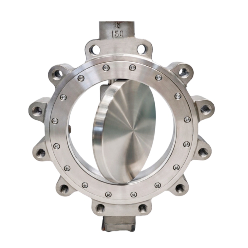
  • How Does a Butterfly Valve Open and Close? Full Operating Guide | GEKO Valve
    How Does a Butterfly Valve Open and Close? Full Operating Guide | GEKO Valve
    Oct 09, 2026
    How Does a Butterfly Valve Open and Close? Full Operating Guide Butterfly valves are the most widely used quarter-turn flow control devices in industrial and municipal piping systems. Many engineers and procurement specialists select industrial butterfly valves for their compact size and cost-saving advantages, yet few fully understand the complete mechanical process of how a butterfly valve opens and closes. Unlike linear-stroke gate valves and globe valves, butterfly valves rely on precise rotary motion to change pipeline flow status. This article clearly explains the opening and closing working process, mechanical logic of different valve designs, actuation modes, and sealing coordination principles. 1. Basic Open and Close Principle of Butterfly Valves The entire opening and closing action of a butterfly valve is completed through a 90-degree quarter-turn rotation. The core moving parts include the valve stem and internal butterfly disc. The stem receives torque from manual or automated actuators and drives the disc to rotate horizontally inside the pipeline bore, realizing full opening, full closing, and intermediate throttling states. Closing Process (90° → 0°): The disc gradually rotates perpendicular to the fluid flow direction, continuously narrowing the flow passage. When reaching 0 degrees, the disc completely presses against the valve seat, blocking the pipeline and achieving tight shutoff. Opening Process (0° → 90°): The disc rotates parallel to the fluid direction, gradually expanding the flow area. At 90 degrees, the disc is fully opened, minimizing flow resistance and allowing maximum fluid passage. This simple rotary operation is what makes wafer butterfly valves and lug butterfly valves so popular for large-bore piping. 2. Complete Mechanical Action Process   The opening and closing cycle follows a fixed mechanical transmission chain, ensuring accurate and stable operation: First, the operating device (lever, gearbox, pneumatic or electric actuator) outputs rotational torque. The torque is transmitted to the central valve stem through the driving shaft. The integrated stem and disc structure rotates synchronously without idle travel. During movement, the disc gradually separates from or compresses against the sealing seat. Finally, the mechanical limit device locks the angle to complete opening or closing positioning. 3. Different Opening & Closing Logic by Valve Structure Concentric and offset butterfly valves have obvious differences in opening and closing friction, which directly affects service life and operating stability: 3.1 Concentric Butterfly Valve Operation Concentric butterfly valves have overlapping centers of the stem, disc, and pipeline. During every opening and closing stroke, the disc keeps continuous contact and friction with the seat. The operation is simple and cost-effective, suitable for low-frequency switching of conventional water treatment and HVAC pipelines. 3.2 Triple Offset Butterfly Valve Zero-Friction Operation Triple offset butterfly valves adopt a three-dimensional offset structure. During the opening process, the disc instantly separates from the seat without friction. During closing, the disc only contacts the seat at the final locking position. This zero-friction opening and closing mechanism greatly reduces seat wear, making this style of heavy duty butterfly valves suitable for high-temperature, high-pressure, and frequent switching industrial pipelines. 4. Sealing Coordination During Opening and Closing Different sealing types match different opening and closing mechanical characteristics: 4.1 Soft Seated Butterfly Valve Soft seated butterfly valves with EPDM or NBR seats rely on elastic compression to achieve zero leakage when fully closed. During closing, the disc gently squeezes the elastic seat to fill tiny gaps. During opening, the elastic seat resets automatically. This flexible sealing opening and closing mode ensures bubble-tight shutoff for clean water and gas media. 4.2 Metal Seated Butterfly Valve Metal seated butterfly valves adopt precision metal-to-metal matching. The opening and closing process realizes rigid mechanical fitting and separation. With high wear resistance and temperature resistance, they maintain stable switching performance in harsh working conditions such as high-temperature steam and abrasive slurry. 5. Opening and Closing Modes of Automated Butterfly Valves Modern industrial pipelines use automated butterfly valves to realize intelligent opening and closing control: Pneumatic Butterfly Valve: Driven by compressed air, it completes fast opening and closing strokes in seconds. With explosion-proof advantages, it is widely used in chemical and petrochemical pipeline switching. Electric Butterfly Valve: Driven by electric actuators, it features stable speed, precise angle positioning, and remote signal control. It supports delayed opening/closing and intermediate positioning, suitable for intelligent pipeline systems. Manual Butterfly Valve: Operated by lever or gear handwheel, it realizes on-site manual opening and closing, economical and convenient for low-frequency operation scenarios. 6. Common Opening & Closing Faults and Causes Valve jamming: Caused by sediment deposition, seat aging, or insufficient actuator torque Incomplete closing and leakage: Disc offset, seat wear, or foreign matter blocking the sealing surface Slow opening and closing speed: Pneumatic air pressure insufficiency or electric actuator parameter deviation 7. GEKO Valve Precise Opening & Closing Performance All GEKO butterfly valves adopt optimized rotary motion structure, ensuring flexible, smooth, and accurate opening and closing actions. Our full product range including wafer, lug, soft seat, metal seat, and triple offset butterfly valves achieves zero-friction switching, stable sealing, and long service life. Automated modulating butterfly valves support arbitrary angle opening and closing, meeting isolation and throttling control requirements of modern industrial piping systems.
    CZYTAJ WIĘCEJ
  • What Is the Role of a Butterfly Valve in Piping Systems? | GEKO Valve
    What Is the Role of a Butterfly Valve in Piping Systems? | GEKO Valve
    Oct 09, 2026
    What Is the Role of a Butterfly Valve in Piping Systems? Industrial and municipal piping networks transport liquids, gases and slurries across vast facilities, requiring reliable flow control hardware to keep operations safe and predictable. As a popular quarter-turn valve, the butterfly valve performs multiple core functions within piping systems. Its compact build, lightweight body and flexible operating modes make it a go-to choice for many pipeline designs, from large water mains to chemical processing lines. This article breaks down the key roles butterfly valves play in piping systems and where their strengths shine. 1. Fluid Isolation for Pipeline Maintenance & Emergency Shutoff One primary role of a butterfly valve is positive isolation. When a pipe segment, pump or downstream equipment needs inspection or repair, operators close the butterfly valve to fully cut off fluid flow. In emergency scenarios such as pipeline overpressure or equipment failure, it can rapidly shut down the line to prevent spillage and system damage. Lug and flange butterfly valves are commonly used for isolation duties, with PTFE or EPDM seats delivering tight shutoff performance. 2. Flow Throttling and Flow Regulation Beyond simple on/off service, butterfly valves are widely used for throttling flow. By rotating the disc to partial opening positions, the valve adjusts the cross-sectional flow area, controlling the volume and velocity of fluid moving through the piping. This function helps stabilize pressure and maintain consistent flow rates for processes like water distribution, HVAC circulation and chemical transfer. Note that precise throttling requires proper material selection to avoid disc erosion from high-speed media. 3. Pressure Control and Surge Mitigation Butterfly valves assist in managing pipeline pressure. Gradual opening or closing can moderate pressure spikes caused by pump start-up and shutdown. In large-diameter piping systems, slow-actuated butterfly valves help reduce water hammer effects that may damage pipe fittings and instruments. Pneumatic or electric actuators are often paired with butterfly valves for automated pressure regulation in modern piping networks.   4. Diversion and Flow Direction Switching In multi-branch piping layouts, sets of butterfly valves work together to divert fluid to different branches. For example, in water treatment plants, they switch flow between filter banks, or in district heating systems, they redirect hot water to different building zones. This eliminates the need to shut down the entire piping system when rerouting process media. 5. Backflow Prevention (Auxiliary Function) While butterfly valves are not dedicated check valves, properly specified butterfly valves can help limit unwanted reverse flow in certain low-risk piping applications. For critical backflow protection, they are usually combined with dedicated check valves as part of a complete piping safety assembly. Key Benefits of Butterfly Valves for Piping Networks Space-saving design: Much thinner than gate or globe valves, ideal for tight pipe rack installations Light weight: Reduces structural load on pipe supports, lowering overall project cost Fast quarter-turn operation: Manual lever, gear, pneumatic or electric actuation options available Wide size range: Works for both small process lines and large diameter main pipelines Corrosion-resistant options: Lined butterfly valves available for corrosive chemical media Selection Tips According to Piping Roles Choose resilient seated butterfly valves for water and wastewater isolation tasks. For corrosive fluids, PTFE lined butterfly valves are recommended. If automatic control is required, specify pneumatic or electric actuators to integrate with plant control systems. Confirm pressure class, flange standard and seat material to match your piping medium and operating temperature. Summary Within piping systems, butterfly valves serve five major purposes: fluid isolation, flow throttling, pressure management, flow diversion and auxiliary backflow control. Thanks to their compact footprint and versatile actuation choices, butterfly valves deliver dependable flow control across water, chemical, power and HVAC piping networks. Selecting the correct butterfly valve design ensures stable, long-term pipeline operation and reduces unplanned downtime.
    CZYTAJ WIĘCEJ
  • How Do Butterfly Valves Work in Water Treatment Plants? | GEKO Valve
    How Do Butterfly Valves Work in Water Treatment Plants? | GEKO Valve
    Oct 09, 2026
    How Do Butterfly Valves Work in Water Treatment Plants? Water treatment facilities rely on stable, cost-effective flow control equipment to manage raw water intake, chemical dosing, filtration, disinfection and effluent discharge. Butterfly valves are widely preferred across all stages of water treatment thanks to their compact size, fast quarter-turn operation, light weight and competitive pricing. Compared with bulky gate valves, butterfly valves save installation space and reduce structural load for large-diameter pipelines commonly seen in water plants. This article explains how butterfly valves function in key water treatment processes and their practical operational advantages. Core Working Principle for Water Treatment Service A butterfly valve uses a circular disc mounted on a central shaft. When the valve rotates 90 degrees, the disc turns parallel or perpendicular to fluid flow. At the fully open position, water flows with minimal resistance; at the closed position, the disc presses against the seat to shut off flow. Between open and closed angles, partial rotation enables throttling for controlled water flow rates. Most water treatment butterfly valves use resilient rubber seats such as EPDM, delivering bubble-tight shutoff for clean and wastewater media.   Typical Applications Inside Water Treatment Plants 1. Raw Water Intake & Pump Station Butterfly valves are installed at intake lines and pump outlets to isolate pipelines during pump maintenance. They quickly cut off raw water from rivers, lakes or reservoirs, protecting downstream filtration units. Large wafer or lug type butterfly valves are commonly selected here due to easy installation between pipe flanges. 2. Coagulation, Flocculation and Sedimentation Tanks Within sedimentation basins, butterfly valves regulate flow between treatment chambers. Operators adjust the disc angle to balance water velocity, supporting stable floc formation and solid settling. Manual or gear-operated versions are widely used for frequent on-off and moderate throttling tasks. 3. Filtration Systems Sand filters and activated carbon filter banks use butterfly valves to switch between filtration and backwash cycles. The valves isolate individual filter units so one tank can undergo backwashing without shutting down the whole treatment line. EPDM seats resist wear from periodic flushing and particle-laden water. 4. Disinfection and Chemical Dosing Lines For chlorine, sodium hypochlorite or pH adjustment chemical pipelines, lined butterfly valves prevent corrosion from chemical additives. They provide reliable isolation for maintenance of dosing skids and mixing chambers. 5. Effluent Discharge and Wastewater Outlet Before treated water is released, butterfly valves control discharge flow and act as emergency shutoff devices. Lug style butterfly valves are often chosen for end-of-line service, allowing blind flange isolation when required. Key Selection Considerations for Water Treatment Butterfly Valves Seat material: EPDM is standard for clean water; choose stronger wear-resistant seats for wastewater with suspended solids Body material: Ductile iron is the mainstream cost-effective option for water projects Actuation: Manual gearbox for occasional operation; pneumatic or electric actuators for automated plant SCADA control Pressure rating: Match pipeline working pressure and surge pressure from pump startup and shutdown Valve type: Wafer butterfly valves for compact installation; lug butterfly valves for dead-end service Advantages of Butterfly Valves in Water Plants Their lightweight design lowers pipeline support costs, while fast quarter-turn operation speeds up emergency shutdown. They are easy to automate for modern smart water plants, and require less maintenance than many alternative valves. The main limitation is that standard resilient seated butterfly valves are not suitable for high-pressure steam or highly abrasive heavy slurry, which needs other valve solutions. Summary From raw water intake through filtration, chemical treatment to final discharge, butterfly valves serve as versatile flow isolation and throttling components across the full water treatment workflow. Properly sized butterfly valves with suitable seat and body materials help water plants maintain stable operation, reduce downtime and cut overall project and maintenance costs.
    CZYTAJ WIĘCEJ
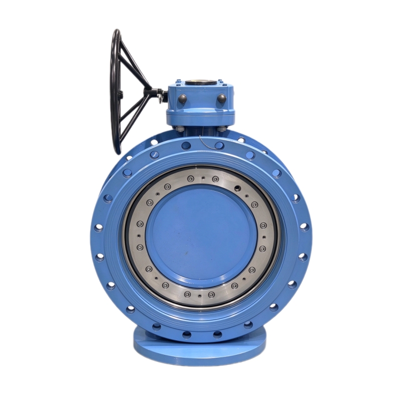
  • What Is a Butterfly Valve and What Are Its Key Components? | GEKO Valve
    What Is a Butterfly Valve and What Are Its Key Components? | GEKO Valve
    Sep 29, 2026
      What Is a Butterfly Valve and What Are Its Key Components? A butterfly valve is a popular quarter-turn flow control device widely used in municipal and industrial piping systems to regulate, throttle, or completely shut off fluid flow. Its slim, lightweight design makes it far more space-saving than ball valves or gate valves, especially for large-diameter pipelines. Many new buyers and plant engineers want to understand exactly what a butterfly valve is and how each internal part works together to deliver reliable performance. This article breaks down the definition, core function, and all key components of a butterfly valve.   Definition and Core Function of a Butterfly Valve At its simplest, a butterfly valve controls fluid by rotating a circular disc inside the pipeline. A 90-degree rotation switches the valve between fully open and fully closed positions. It can also stay at intermediate angles for throttling flow. Wafer butterfly valves and lug butterfly valves are the two most common body styles, while offset designs like triple offset butterfly valves handle demanding high-temperature and high-pressure applications. Butterfly valves work with water, air, gas, and many chemical media across water treatment, HVAC, power, and chemical processing industries. Key Components of a Butterfly Valve 1. Valve Body The valve body forms the main pressure-containing shell and connects to the pipeline. Wafer-style bodies fit between two pipe flanges without bolt lugs. Lug bodies have threaded lugs built into the valve to hold flanges securely. Heavy-duty metal seated butterfly valves use cast iron, ductile iron, stainless steel, or alloy steel bodies to withstand harsh working environments. 2. Butterfly Disc The disc is the circular plate inside the body that blocks or allows fluid passage. It rotates with the valve stem. The disc shape directly impacts flow resistance. Concentric valves use a flat disc; double offset and triple offset valves use contoured discs to reduce seat friction during rotation. For corrosive media, discs are coated or made from stainless steel to extend service life. 3. Valve Stem The stem is a shaft that passes through the valve body and attaches firmly to the disc. It transfers torque from the actuator or handwheel to rotate the disc. Most stems are made of high-strength stainless steel to resist torsion and corrosion. Many designs use a one-piece stem and disc connection to eliminate play and improve control precision. 4. Seat / Sealing Ring The seat creates the sealing contact surface between the disc and valve body. Soft seated butterfly valves use elastomer seats such as EPDM or PTFE to achieve bubble-tight shutoff for clean media. Metal seated versions use metal-to-metal sealing surfaces, suited for high temperature, abrasive, or steam media where rubber seats cannot survive.   5. Stem Seals & Gaskets Stem seals prevent fluid leakage along the stem where it exits the valve body. Packing rings or O-rings form the primary barrier. They are critical to prevent fugitive emissions, especially for chemical and oil & gas applications. 6. Actuator / Operating Unit The actuator supplies torque to turn the stem and disc. Manual versions use a handwheel or lever. Pneumatic butterfly valves use compressed air for fast on/off or modulating control. Electric butterfly valves allow remote automated operation and precise flow adjustment. Positioners can be fitted to modulating actuators to maintain exact disc angles. How These Components Work Together When the actuator turns the valve stem, the disc rotates inside the body. In closed position, the disc presses against the seat to block fluid. When opened, the disc turns parallel to flow so media can pass through. All parts must be properly matched to the working pressure, temperature, and medium. A mismatch in seat or disc material will quickly cause leakage and premature failure. GEKO Valve Butterfly Valve Range GEKO Valve supplies complete butterfly valve assemblies with high-quality components. Our range includes soft seated and metal seated, concentric, double offset and triple offset butterfly valves, available in wafer, lug, flanged designs with manual, pneumatic or electric actuators for industrial and municipal projects worldwide. 9 Core SEO Keywords: Wafer Butterfly Valve, Lug Butterfly Valve, Triple Offset Butterfly Valve, Soft Seated Butterfly Valve, Metal Seated Butterfly Valve, Pneumatic Butterfly Valve, Electric Butterfly Valve, Automated Butterfly Valve, Heavy Duty Butterfly Valve
    CZYTAJ WIĘCEJ
  • How Does a Butterfly Valve Control Fluid Flow? Complete Working Guide | GEKO Valve
    How Does a Butterfly Valve Control Fluid Flow? Complete Working Guide | GEKO Valve
    Sep 29, 2026
      How Does a Butterfly Valve Control Fluid Flow? Complete Working Guide Butterfly valves are widely recognized as the most cost-effective and space-efficient fluid control devices for municipal and industrial pipelines. Unlike ball valves that provide full straight-line flow or gate valves designed only for full open or full closed isolation, industrial butterfly valves feature unique rotary disc mechanics that enable flexible fluid management. Many system designers and plant operators wonder: how does a butterfly valve control fluid flow accurately and stably? This guide explains the full flow control mechanism, different working states of butterfly valves, structural differences between product types, and practical flow control performance in modern piping systems. 1. Basic Fluid Control Principle of Butterfly Valves The core fluid control method of a butterfly valve relies on a90-degree quarter-turn rotary disc. Installed vertically in the pipeline center, the butterfly disc rotates along the valve stem to change the effective flow area inside the pipe. By adjusting the disc angle, the valve precisely changes flow resistance, fluid velocity, and pipeline pressure, thereby realizing three core flow control functions: full flow passage, partial throttling, and complete fluid shutoff. This simple and reliable rotary flow control method is the key reason why wafer butterfly valves, lug butterfly valves, and offset butterfly valves are widely used in large-diameter water, gas, and low-viscosity process fluid pipelines. 2. Three Core Flow Control States 2.1 Full Flow Open State When the disc rotates 90 degrees and is parallel to the fluid direction, the pipeline reaches maximum flow capacity. Although the disc remains inside the pipeline, the streamlined disc structure minimizes flow resistance. In this state, the industrial butterfly valve allows unrestricted fluid transmission, suitable for long-term circulating pipeline operation and maximum flow supply scenarios. 2.2 Precise Throttling and Flow Regulation State The biggest advantage of butterfly valves in fluid control is their excellent throttling performance. When the disc stays at any angle between 20% and 70% opening, it forms an adjustable shielding area inside the pipeline. The larger the shielding area, the higher the flow resistance and the lower the fluid flow rate. Modulating butterfly valves with electric or pneumatic actuators can maintain stable opening angles, realizing continuous and accurate flow balancing, pressure adjustment, and fluid distribution control for industrial systems.   2.3 Full Closed Fluid Shutoff State When the disc rotates to 0 degrees and is completely perpendicular to the fluid flow, the disc closely fits the valve seat to block the entire flow passage. Soft seated butterfly valves use elastic seat deformation to achieve bubble-tight zero leakage for clean media, while metal seated butterfly valves rely on precision metal fitting to block high-temperature, high-pressure and abrasive fluids, achieving reliable pipeline isolation and fluid cut-off. 3. How Different Butterfly Valve Types Optimize Flow Control Different butterfly valve structures deliver completely different fluid control effects, adapting to diverse industrial working conditions: 3.1 Concentric Butterfly Valves for General Flow Control Concentric butterfly valves feature coincident stem, disc and pipeline centers, providing stable basic flow regulation and isolation. They are ideal for conventional water treatment, HVAC, and fire protection pipelines with normal temperature and low pressure, offering economical and practical fluid control performance. 3.2 Double and Triple Offset Butterfly Valves for Heavy-Duty Flow Control Triple offset butterfly valves and double offset butterfly valves adopt a unique offset structure. The disc avoids friction with the seat during rotation, ensuring smooth and stable angle adjustment even under high pressure and high temperature. These heavy duty butterfly valves provide precise flow control for steam, flue gas, corrosive chemical media, and high-cycle industrial process pipelines. 3.3 Wafer vs Lug Type Flow Control Features Wafer butterfly valves feature ultra-thin bodies with low flow resistance, suitable for compact pipeline systems requiring stable large-flow control. Lug butterfly valves support unilateral pipeline disassembly while maintaining system flow control safety, facilitating segmented pipeline maintenance without affecting the overall fluid system. 4. How Actuators Support Accurate Fluid Control Stable fluid control cannot be achieved by the valve body alone; the actuator determines control accuracy and automation level: Manual Butterfly Valves: Realize simple on-site flow adjustment and pipeline isolation, suitable for low-frequency control scenarios. Pneumatic Butterfly Valves: Equipped with positioners to correct angle deviation, maintaining stable flow rate under fluctuating pipeline pressure, ideal for explosion-proof industrial fluid systems. Electric Automated Butterfly Valves: Support remote signal adjustment and proportional flow control, matching intelligent industrial systems to realize automatic fluid management and precise flow distribution. 5. Key Advantages of Butterfly Valve Fluid Control Achieve dual functions of fluid isolation and flow throttling with a single valve device Suitable for large-diameter pipeline flow control with low cost and small installation space Smooth rotary operation ensures stable fluid adjustment without pipeline surge Multiple product types adapt to clean, corrosive, high-temperature and abrasive fluid media Support manual and automatic intelligent fluid control for modern industrial systems 6. GEKO Valve Reliable Fluid Control Butterfly Valve Solutions GEKO Valve provides a full range of high-performance butterfly valves for precise industrial fluid control. Our product lineup includes soft seated and metal seated butterfly valves, concentric and triple offset butterfly valves, wafer and lug type butterfly valves, as well as manual, pneumatic and electric automated butterfly valves. All products deliver stable flow regulation, reliable shutoff performance and long service life, providing accurate and efficient fluid control solutions for water treatment, HVAC, chemical, power, and municipal engineering systems. 9 Core SEO Keywords: Industrial Butterfly Valve, Triple Offset Butterfly Valve, Soft Seated Butterfly Valve, Metal Seated Butterfly Valve, Wafer Butterfly Valve, Lug Butterfly Valve, Modulating Butterfly Valve, Heavy Duty Butterfly Valve, Automated Butterfly Valve
    CZYTAJ WIĘCEJ
  • Jaki jest mechanizm działania zaworu motylkowego? | Zawór GEKO
    Jaki jest mechanizm działania zaworu motylkowego? | Zawór GEKO
    Sep 21, 2026
     Jaki jest mechanizm działania zaworu motylkowego?Zawory motylkowe to jedne z najbardziej wszechstronnych zaworów regulacyjnych ćwierćobrotowych stosowanych w nowoczesnych instalacjach przemysłowych i komunalnych. Chociaż większość inżynierów zna ich szybkie przełączanie i kompaktową konstrukcję, przemysłowe zawory motylkoweWiele osób nie do końca rozumie kompletny mechanizm działania, który umożliwia niezawodną izolację cieczy, odporność na ciśnienie i precyzyjną modulację przepływu w różnych rodzajach zaworów motylkowych. W przeciwieństwie do zaworów kulowych, które wykorzystują uszczelnienie kulowe lub zasuw o pionowym ruchu, zawory motylkowe wykorzystują unikalną konstrukcję mechaniczną z obrotowym dyskiem. Niniejszy artykuł dogłębnie analizuje pełny mechaniczny mechanizm działania zaworów motylkowych, w tym przenoszenie momentu obrotowego, logikę ruchu dysku, mechanikę uszczelnienia zaworów motylkowych z miękkim i metalowym gniazdem, zasady działania przesunięcia oraz koordynację siłowników w automatycznych zaworach motylkowych.1. Ogólny przegląd mechanizmu działania mechanicznegoCały mechanizm działania przepustnicy opiera się na przekładnia mechaniczna obrotowa i dopasowanie dynamiki płynówSiłownik generuje moment obrotowy, który jest przenoszony przez trzpień zaworu, napędzając wewnętrzny dysk motylkowy, który wykonuje obrót o ćwierć obrotu o 90 stopni. Zmieniając kąt nachylenia dysku wewnątrz otworu rurociągu, zawór zmienia pole przekroju poprzecznego przepływu, realizując w ten sposób trzy podstawowe funkcje mechaniczne: odcięcie przepływu cieczy, pełny przepływ oraz regulację dławienia pośredniego. Cała konstrukcja mechaniczna charakteryzuje się mniejszą liczbą części przekładni, prostszą logiką ruchu i szybszą reakcją niż w przypadku wielosuwowych zaworów przemysłowych.2. Rdzeń mechanizmu przekładni mechanicznej Przeniesienie momentu obrotowego stanowi główne źródło napędu zaworu motylkowego. Kompletny łańcuch przekładni mechanicznej składa się z siłownika, trzpienia zaworu, sworznia wału i tarczy motylkowej, zapewniając precyzyjną konwersję mocy i wyjściową regulację ruchu.Gdy siłownik otrzymuje sygnał otwarcia lub zamknięcia, generuje moment obrotowy i przekazuje go na pionowy trzpień zaworu. Trzpień zaworu jest zamocowany do tarczy motylkowej za pomocą precyzyjnych sworzni wału, co eliminuje jałowy obrót i zapewnia synchroniczny ruch kątowy. Wał trzpienia opiera się na precyzyjnych tulejach wału i uszczelnieniu, które zmniejszają opory tarcia, zapewniając elastyczny i stabilny obrót bez zacięć. Ten mechaniczny mechanizm przekładniowy przekształca energię elektryczną, pneumatyczną lub ręczną w ruch obrotowy, sprawnie otwierając i zamykając zawór.3. Mechanizm mechaniczny kontroli przepływu tarczowegoTarcza motylkowa jest elementem wykonawczym sterowania przepływem, a jej kątowe przemieszczenie bezpośrednio określa stan przepływu w rurociągu. Różne kąty otwarcia odpowiadają różnym stanom mechanicznej kontroli przepływu.W pozycji zamkniętej pod kątem 0 stopni, tarcza jest całkowicie prostopadła do kierunku przepływu cieczy, tworząc pełną barierę dla medium. Pod wpływem ciśnienia medium, tarcza ściśle przylega do gniazda zaworu, zapewniając mechaniczne uszczelnienie kompresyjne. W pozycji całkowicie otwartej pod kątem 90 stopni, tarcza jest równoległa do kierunku przepływu cieczy, minimalizując opory przepływu i umożliwiając maksymalny przepływ cieczy. Pod dowolnym kątem między 0 a 90 stopni, tarcza tworzy zachodzącą na siebie strukturę dławiącą z otworem rurociągu, wykorzystując mechaniczną okluzję do zmiany prędkości przepływu i ciśnienia, realizując ciągłą regulację przepływu.4. Mechanizm uszczelniający (uszczelnienie miękkie i twarde)Niezawodna skuteczność odcinania zaworów motylkowych wynika z dwóch różnych mechanizmów uszczelniających, które można stosować w różnych warunkach pracy w przemyśle: 4.1 Mechanizm uszczelniający z elastycznym dociskiem (miękkie gniazdo)Zawory motylkowe z miękkim siedziskiem Wykorzystują elastyczne gniazda polimerowe, takie jak EPDM i Viton. Podczas ruchu zamykającego, tarcza mechanicznie ściska elastyczne gniazdo, powodując mikroodkształcenia sprężyste. Odkształcone gniazdo wypełnia niewielkie szczeliny mechaniczne między krawędzią tarczy a korpusem zaworu, zapewniając szczelność bez przecieków. Ten elastyczny mechanizm kompensacji dostosowuje się do niewielkich tolerancji obróbki i zmian ciśnienia w rurociągu, zapewniając szczelne zamknięcie przepustnic z miękkim gniazdem w normalnych warunkach temperatury i niskiego ciśnienia.4.2 Precyzyjny mechaniczny mechanizm uszczelniający (gniazdo metalowe)Zawory motylkowe z metalowym siedziskiem Zastosowano sztywny mechanizm uszczelniający metal-metal. Po precyzyjnej obróbce mechanicznej i docieraniu lustrzanym, tarcza i gniazdo tworzą precyzyjnie dopasowaną parę uszczelniającą. Dzięki sztywnemu mechanicznemu stykowi i sile samodokręcania pod średnim ciśnieniem, zawór zapewnia stabilne uszczelnienie w wysokich temperaturach, wysokim ciśnieniu i warunkach ściernych. Ta mechaniczna konstrukcja uszczelniająca jest odporna na odkształcenia związane ze starzeniem i zapewnia długotrwałą, wielocykliczną eksploatację przemysłowych zaworów motylkowych o dużej wytrzymałości.5. Zawór motylkowy offsetowy z mechanizmem mechanicznym o zerowym tarciuZawory motylkowe koncentryczne i offsetowe różnią się zasadniczo pod względem logiki działania mechanicznego, co determinuje ich żywotność i odporność na ciśnienie.Koncentryczne zawory motylkowe charakteryzują się całkowicie zbieżnym środkiem trzonu, tarczy i przewodu. Tarcza utrzymuje stałe tarcie mechaniczne z gniazdem podczas każdego cyklu otwierania i zamykania, co prowadzi do szybkiego zużycia gniazda. W przeciwieństwie do tego, wycieczkaprzesunięcie zawory motylkowe Zawory motylkowe z podwójnym offsetem wykorzystują przestrzenną, przesuniętą konstrukcję mechaniczną. W początkowej fazie obrotu tarcza automatycznie oddziela się od gniazda uszczelniającego bez kontaktu ciernego. Dopiero pod kątem zamknięcia tarcza styka się z gniazdem, ustalając położenie i uszczelniając. Ten mechanizm działania bez tarcia znacznie zmniejsza zużycie podzespołów, poprawia trwałość zaworu i dostosowuje się do ciężkich warunków pracy z częstym przełączaniem w przypadku zaworów motylkowych z offsetem.6. Zautomatyzowany mechanizm koordynacji siłownikówRóżne siłowniki tworzą różne mechanizmy automatycznej obsługi, pasujące do nowoczesnych inteligentnych systemów rurociągowych:Mechanizm pneumatycznego zaworu motylkowego:Zamienia energię ciśnienia sprężonego powietrza na mechaniczny moment obrotowy, charakteryzuje się szybkim działaniem i odpornością mechaniczną na wybuchy, nadaje się do stosowania w niebezpiecznych środowiskach przemysłowych.Mechanizm zaworu motylkowego elektrycznego:Wykorzystuje napęd silnikowy i wzmocnienie momentu obrotowego reduktora w celu osiągnięcia precyzyjnego pozycjonowania kąta, obsługując zdalne sterowanie sygnałem i regulację proporcjonalną.Mechanizm ręcznego zaworu motylkowego:Opiera się na ręcznym mechanicznym wprowadzaniu momentu obrotowego, prostej strukturze przekładni, jest stabilny i niezawodny przy pracy o niskiej częstotliwości.7. Zalety przemysłowe mechanizmu mechanicznego zaworu motylkowegoUnikalna struktura działania mechanicznego zapewnia przemysłowy zawory motylkowe Z niezastąpionymi zaletami przemysłowymi: kompaktowa konstrukcja mechaniczna oszczędza miejsce na instalację zaworów motylkowych międzykołnierzowych i przelotowych, prosta konstrukcja przekładni zmniejsza awaryjność, mechanizm przesunięcia bez tarcia wydłuża żywotność zaworów motylkowych z potrójnym przesunięciem, a elastyczne przesunięcie kątowe spełnia podwójną funkcję – odcięcia i dławienia – w przypadku zaworów motylkowych modulacyjnych. Te właściwości mechaniczne sprawiają, że różne typy zaworów motylkowych są preferowanym rozwiązaniem w przemysłowych i komunalnych systemach sterowania przepływem cieczy o dużej średnicy.8. Zawór GEKO o wysokiej precyzji konstrukcji mechanicznejGEKO Valve optymalizuje wewnętrzny mechanizm działania wszystkich przemysłowych przepustnic. Wykorzystując technologię precyzyjnego odlewania, obróbki CNC i docierania lustrzanego, nasze przepustnice międzykołnierzowe, przepustnice z otworami przelotowymi, przepustnice z metalowym i miękkim gniazdem charakteryzują się równomiernym przenoszeniem momentu obrotowego, elastycznością obrotu, precyzyjnym pozycjonowaniem tarczy i stabilnym uszczelnieniem. Kompletna seria produktów, obejmująca przepustnice koncentryczne, z podwójnym i potrójnym offsetem, w pełni spełnia wymagania mechaniczne różnych rurociągów przemysłowych niskiego, średniego i wysokiego ciśnienia.9 podstawowych słów kluczowych SEO: Przemysłowy zawór motylkowy, Zawór motylkowy z potrójnym offsetem, Zawór motylkowy z miękkim siedziskiem, Zawór motylkowy z metalowym siedziskiem, Zawór motylkowy z płytką, Zawór motylkowy z otworami, Modulacyjny zawór motylkowy, Zawór motylkowy o dużej wytrzymałości, Automatyczny zawór motylkowy
    CZYTAJ WIĘCEJ
  • W jaki sposób zawory motylkowe regulują przepływ w nowoczesnych systemach?
    W jaki sposób zawory motylkowe regulują przepływ w nowoczesnych systemach?
    Sep 21, 2026
    W jaki sposób zawory motylkowe regulują przepływ w nowoczesnych systemach?Nowoczesne przemysłowe i komunalne systemy przepływu cieczy wymagają niezawodnych komponentów, które umożliwiają zarówno odcięcie przepływu, jak i precyzyjną modulację. Wśród rozwiązań zaworów ćwierćobrotowych, zawory motylkowe wyróżniają się kompaktowymi wymiarami, ekonomicznością i sprawdzoną skutecznością regulacji przepływu w rurociągach o dużej średnicy. Podczas gdy wielu użytkowników kojarzy zawory motylkowe wyłącznie z prostym odcięciem, odpowiednio dobrane zawory motylkowe mogą zapewnić stabilne dławienie przepływu cieczy, gazów i mediów o niskiej ścieralności. W tym artykule wyjaśniono dokładnie, jak zawory motylkowe regulują przepływ, ich charakterystykę sterowania, odpowiednie zakresy pracy, dopasowanie siłowników oraz rzeczywiste ograniczenia w nowoczesnych systemach procesowych.Podstawowy mechanizm regulacji przepływu dla zaworów motylkowychZawór motylkowy reguluje przepływ poprzez obrót okrągłej tarczy wewnątrz rury. Tarcza obraca się wokół centralnego wału, podłączonego do napędu ręcznego, pneumatycznego lub elektrycznego. Gdy tarcza znajduje się równolegle do osi rurociągu, zawór otwiera się całkowicie, zapewniając maksymalną przepustowość. Obracając się w kierunku pozycji zamkniętej, tarcza blokuje część kanału przepływu, tworząc zmienny opór przepływu, który moduluje prędkość medium i objętościowe natężenie przepływu. Przy obrocie o 90 stopni tarcza jest ustawiona prostopadle do przepływu, aby zapewnić zamknięcie. W przeciwieństwie do zaworów kulowych, które oferują niemal niezakłócony przepływ o pełnym prześwicie, tarcza motylkowa zawsze pozostaje w kanale przepływu, nawet przy pełnym otwarciu. Ta naturalna przeszkoda generuje spadek ciśnienia, który staje się kluczową fizyczną podstawą dławienia i regulacji przepływu.Charakterystyki przepływu zaworów motylkowychWiększość standardowych zaworów motylkowych spełnia zmodyfikowana charakterystyka przepływu stałoprocentowegoNiewielkie korekty kątowe w zakresie środkowego skoku powodują stosunkowo duże zmiany objętości przepływu. Oznacza to, że najlepsza wydajność dławienia występuje zazwyczaj w zakresie od 20% do 70% otwarcia tarczy. Praca w pozycjach bliskich całkowitemu zamknięciu lub prawie pełnym otwarciu zmniejsza dokładność regulacji: pozycje bliskie zamknięciu stwarzają ryzyko kawitacji i erozji przy dużej prędkości; pozycje bliskie pełnemu otwarciu powodują minimalne zmiany przepływu nawet przy znacznym obrocie tarczy.W przypadku wymagających pętli sterowania, specjalnie wyprofilowane tarcze umożliwiają dostosowanie krzywych przepływu do liniowych wymagań procesu, poprawiając stabilność w zastosowaniach z ciągłą modulacją przepływu.Wybór siłownika do dokładnej regulacji przepływuDobre wyniki dławienia zależą nie tylko od konstrukcji korpusu zaworu, ale także od kompatybilnego sterowania:Zawory motylkowe ręczne: Nadaje się jedynie do wstępnej, rzadkiej regulacji ręcznej; nie obsługuje automatycznej kontroli przepływu w pętli zamkniętej.Siłowniki pneumatyczne z pozycjonerami: Preferowana w branży opcja do modulacji. Pozycjonery zaworów przetwarzają sygnały sterujące na precyzyjne kąty tarcz, kompensując wahania ciśnienia procesowego i tarcie wału.Siłowniki modulacyjne elektryczne: Idealne dla miejsc bez dostępu do sprężonego powietrza, oferując powtarzalne pozycjonowanie dla nowoczesnych systemów zarządzanych zdalnie.Bez dedykowanego pozycjonera nawet wysokiej jakości zawory motylkowe nie mogą utrzymać stabilnego przepływu o zadanej wartości przy zmieniających się warunkach ciśnienia po stronie wlotowej.Główne ograniczenia stosowania zaworów motylkowych do modulacji przepływu Inżynierowie powinni rozumieć ograniczenia praktyczne, aby uniknąć przedwczesnej awarii podzespołów:Długotrwałe dławienie w pozycjach bliskich zamknięcia może powodować kawitację, wibracje, drgania tarczy i zużycie uszczelnień.Medium ścierne może szybko erodować krawędzie tarcz i powierzchnie uszczelniające w warunkach dławienia przy dużej prędkości.Zawory motylkowe nie są zalecane do precyzyjnego sterowania pętlą krytyczną, w sytuacjach, w których konwencjonalnym wyborem pozostają zawory kulowe.Duża różnica ciśnień na częściowo zamkniętym dysku powoduje znaczne obciążenia momentem obrotowym, co wymaga stosowania siłowników o większych rozmiarach.Typowe zastosowania nowoczesnych systemów do regulacji zaworów motylkowychZawory motylkowe są powszechnie stosowane do regulacji przepływu w układach o dużych rozmiarach, gdzie dominują ograniczenia kosztów i przestrzeni:Zakłady uzdatniania wody: sterowanie dopływem wody surowej, dławienie rurociągów dystrybucyjnychObiegi ogrzewania i chłodzenia HVAC: równoważenie przepływu wody ciepłej i chłodzonejZakłady petrochemiczne: modulacja pętli wody chłodzącej, regulacja przepływu gazu o niskiej korozjiSieci rurociągów miejskich: zarządzanie ciśnieniem i przepływem wody w systemie dystrybucji masowejUkłady pomocnicze elektrowni: regulacja przepływu wody obiegowejNajlepsze praktyki optymalizacji wydajności regulacji przepływu zaworów motylkowychOgranicz działanie dławienia w przedziale 20–70%. Do automatycznych pętli sterowania należy dobrać siłowniki modulacyjne ze sprzężeniem zwrotnym położenia. Oblicz moment obrotowy na podstawie rzeczywistej różnicy ciśnień, a nie tylko nominalnego rozmiaru zaworu. Wybierz odpowiednie materiały gniazd, zgodne z temperaturą procesu i składem chemicznym medium. W przypadku przewidywanej silnej kawitacji należy rozważyć zastosowanie trymera antykawitacyjnego lub alternatywnych typów zaworów.Ostatnie myśliZawory motylkowe zapewniają skuteczną i konkurencyjną cenowo regulację przepływu w wielu nowoczesnych systemach przemysłowych i komunalnych o dużej średnicy. Zasada działania obrotowego dysku umożliwia zarówno izolację, jak i modulację, a wydajność jest ograniczona przez charakterystykę przepływu, konfigurację siłownika i warunki procesu. Dopasowanie konstrukcji zaworu, osprzętu napędowego i zakresu pracy zapewnia stabilną, długotrwałą kontrolę przepływu w instalacji zaworów motylkowych.
    CZYTAJ WIĘCEJ
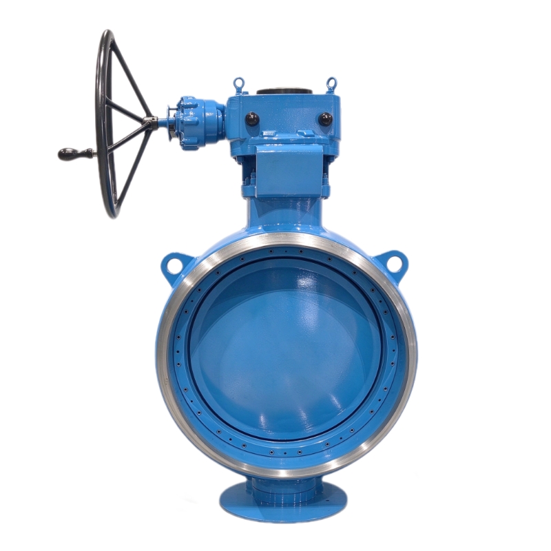
  • Jaka jest zasada działania zaworu motylkowego? Kompletny przewodnik przemysłowy | Zawór GEKO
    Jaka jest zasada działania zaworu motylkowego? Kompletny przewodnik przemysłowy | Zawór GEKO
    Sep 20, 2026
     Zawory motylkowe to niezbędne elementy regulacji przepływu o ćwierćobrotowym obrocie, powszechnie stosowane w instalacjach rurociągowych komunalnych i przemysłowych. Aby prawidłowo dobrać, obsługiwać i konserwować zawory motylkowe, niezbędne jest ich pełne zrozumienie. zasady działaniaW przeciwieństwie do zaworów kulowych, które wykorzystują obrót kuli sferycznej lub zasuw z pionowymi konstrukcjami podnoszącymi, zawory motylkowe wykorzystują unikalny mechanizm obrotowy dysku. Niniejszy artykuł systematycznie wyjaśnia podstawową zasadę działania, logikę działania konstrukcji, zasadę uszczelniania, zasadę dławienia oraz różnice w działaniu różnych typów zaworów motylkowych, zapewniając profesjonalne wsparcie techniczne w zakresie projektowania rurociągów przemysłowych i zastosowań zaworów. 1. Podstawowa zasada działania zaworów motylkowychPodstawowa zasada działania zaworu motylkowego opiera się na Ruch obrotowy o ćwierć obrotu w zakresie 90 stopni wewnętrznego dysku. Trzpień zaworu napędza dysk, obracając go poziomo w zakresie od 0° do 90°, realizując przełączanie i regulację przepływu w rurociągu. Cały proces roboczy jest prosty, wydajny i szybki, bez skomplikowanej mechanicznej konstrukcji przekładni. Stan całkowicie otwarty (90°):Gdy tarcza obraca się równolegle do kierunku przepływu cieczy, kanał przepływowy jest całkowicie otwarty. Ciecz przepływa przez korpus zaworu z minimalnym oporem przepływu, zapewniając wysoką wydajność przesyłu cieczy w rurociągu.Stan całkowicie zamknięty (0°):Gdy tarcza obraca się prostopadle do kierunku przepływu cieczy, jej powierzchnia ściśle przylega do gniazda zaworu. Kanał przepływowy jest całkowicie zablokowany, co zapewnia niezawodną izolację rurociągu i odcięcie przepływu cieczy.Stan dławienia (1°–89°)Tarcza może być ustawiona pod dowolnym kątem pośrednim. Zmieniając powierzchnię zachodzenia tarczy na kanał przepływowy, zawór precyzyjnie kontroluje natężenie przepływu cieczy, prędkość medium i ciśnienie w rurociągu, zapewniając stabilną regulację dławienia. 2. Zasada działania strukturalnego: w jaki sposób główne komponenty działają synergicznieStabilne działanie zaworów motylkowych opiera się na skoordynowanej pracy wielu kluczowych komponentów. Każdy element ma niezależną zasadę działania i tworzy kompletny system sterowania przepływem cieczy:Zasada działania trzpienia zaworowego: Jako rdzeń przenoszący moment obrotowy, trzpień zaworu łączy siłownik z tarczą. Przekształca ręczny, pneumatyczny lub elektryczny moment obrotowy w siłę obrotową tarczy, zapewniając synchroniczne i precyzyjne przełączanie kąta.Zasada sterowania przepływem tarczowym:Opływowy dysk jest elementem wykonawczym do sterowania przepływem cieczy. Jego kąt obrotu bezpośrednio zmienia przekrój poprzeczny przepływu, umożliwiając liniową regulację przepływu i ciśnienia w rurociągu.Zasada pozycjonowania korpusu zaworuKorpus zaworu zapewnia stabilne podparcie montażowe i ochronę przed ciśnieniem. Utrzymuje on położenie trzpienia i gniazda, zapewniając dokładne dopasowanie tarczy podczas zamykania i zapobiegając odchyleniom położenia wpływającym na szczelność.3. Zasada działania uszczelnienia zaworów motylkowychSkuteczność uszczelnienia decyduje o niezawodności odcięcia zaworów motylkowych. W zależności od konstrukcji uszczelnień, zasady działania dzielą się na uszczelnienia miękkie i uszczelnienia twarde, dostosowane do różnych warunków pracy w przemyśle: 3.1 Zasada uszczelnienia miękkiegoZawory motylkowe z miękkim siedziskiem wykorzystują elastyczne materiały, takie jak EPDM, NBR i Viton, jako uszczelnienia. Gdy zawór jest zamknięty, dysk ściska elastyczne siedzisko, powodując mikroodkształcenia i wypełniając wąską szczelinę między dyskiem a siedziskiem. Ta elastyczna zasada uszczelnienia kompresyjnego umożliwiaszczelność bąbelkowa, brak wycieków, nadaje się do czyszczenia mediów w normalnej temperaturze i przy niskim ciśnieniu, takich jak woda i powietrze.3.2 Zasada uszczelniania twardym metalemZawory motylkowe z metalowym gniazdem wykorzystują pary uszczelnień metal-metal z napawaniem stopowym. Dzięki precyzyjnej obróbce mechanicznej i precyzyjnemu docieraniu, metalowy dysk i metalowe gniazdo zapewniają sztywne i ścisłe dopasowanie. Ta mechaniczna zasada uszczelnienia kompresyjnego jest odporna na korozję wysokotemperaturową i średniotemperaturową, zapewniając stabilne uszczelnienie w wysokich temperaturach, wysokim ciśnieniu i agresywnych warunkach pracy.4. Różnice w zasadzie działania: zawory motylkowe koncentryczne i offsetoweZawory motylkowe koncentryczne i offsetowe różnią się zasadniczo logiką działania, co bezpośrednio wpływa na żywotność i odporność na ciśnienie:4.1 Zasada działania zaworu motylkowego koncentrycznegoŚrodek trzpienia, środek tarczy i środek rurociągu pokrywają się całkowicie. Podczas obrotu tarcza stale ociera się o powierzchnię gniazda. Konstrukcja jest prosta i ekonomiczna, odpowiednia do konwencjonalnych warunków pracy przy niskim ciśnieniu i normalnej temperaturze, z niską częstotliwością przełączania.4.2 Zasada działania zaworu motylkowego podwójnego i potrójnego offsetowegoDzięki unikalnej konstrukcji z przesunięciem, tarcza automatycznie oddziela się od powierzchni siedziska w początkowej fazie obrotu i styka się z siedziskiem dopiero w końcowym momencie zamykania. zasada obrotu bez tarcia eliminuje zużycie siedzeń, znacznie zwiększa odporność na ciśnienie i wysoką temperaturę, nadaje się do ciężkich warunków pracy przemysłowej z częstym przełączaniem.5. Zasada działania automatycznych zaworów motylkowychRóżne tryby działania zapewniają zróżnicowaną logikę sterowania pracą zaworów motylkowych, spełniając potrzeby ręcznego i automatycznego sterowania przemysłowego:Zasada obsługi ręcznej:Napędzanie przekładni lub trzpienia za pomocą dźwigni lub koła ręcznego, wyprowadzanie sztucznego momentu obrotowego w celu sterowania obrotem tarczy, możliwość stosowania w instalacjach o niskiej częstotliwości na miejscu.Zasada działania pneumatycznego:Wykorzystuje sprężone powietrze do popchnięcia tłoka siłownika, zamienia energię ciśnienia powietrza na energię mechaniczną obrotową, zapewniając szybkie przełączanie zaworów przy zachowaniu doskonałej odporności na wybuchy.Zasada działania elektrycznegoSilnik elektryczny zapewnia precyzyjną kontrolę momentu obrotowego i kąta, obsługuje zdalne połączenie sygnału i proporcjonalną regulację, realizując inteligentne automatyczne sterowanie rurociągiem.6. Charakterystyka pracy i wartość zastosowania przemysłowegoOparte na unikalnej zasadzie działania z obrotem ćwierćobrotowym, zawory motylkowe charakteryzują się szybką reakcją, niewielkimi oporami przepływu, kompaktową konstrukcją i szerokim zakresem adaptacji do warunków pracy. Spełniają one nie tylko konwencjonalne wymagania dotyczące izolacji rurociągów, ale także zapewniają precyzyjne dławienie przepływu, nieosiągalne dla tradycyjnych zasuw. Dzięki niezawodnej pracy, znajdują szerokie zastosowanie w przemyśle uzdatniania wody, HVAC, przeciwpożarowym, chemicznym, energetycznym i ochrony środowiska.7. Technologia zaworów motylkowych o wysokiej wydajności firmy GEKO ValveFirma GEKO Valve ściśle optymalizuje konstrukcję i mechanizm działania wszystkich zaworów motylkowych. Nasze koncentryczne i potrójnie offsetowe zawory motylkowe wykorzystują technologię precyzyjnego odlewania i polerowania lustrzanego, zapewniając elastyczność obrotu, precyzyjną kontrolę kąta i stabilne uszczelnienie. Zróżnicowane konfiguracje napędu i uszczelnienia w pełni odpowiadają różnym przemysłowym zasadom pracy i wymaganiom aplikacji, zapewniając długoterminowe, stabilne rozwiązania w zakresie kontroli przepływu w globalnych systemach rurociągów przemysłowych.9 podstawowych słów kluczowych SEO: Zasada działania przemysłowego zaworu motylkowego, Wysokowydajny zawór motylkowy, Zawór motylkowy offsetowy, Zawór motylkowy o zerowym przecieku, Zawór przemysłowy ćwierćobrotowy, Mechanizm uszczelniający zaworu motylkowego, Wytrzymały zawór motylkowy, Automatyczny zawór motylkowy, Zawór motylkowy regulujący przepływ
    CZYTAJ WIĘCEJ
1 2 3 4 5 6 7 8 9 10 11 12
W sumie 12strony

zostaw wiadomość

zostaw wiadomość
Jeśli jesteś zainteresowany naszymi produktami i chcesz poznać więcej szczegółów, zostaw wiadomość tutaj, a my odpowiemy tak szybko, jak to możliwe.
składać

Dom

Produkty

kontakt